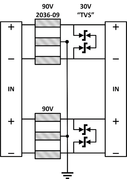
Surge Board

Proposed Surge Arrester Design for Spring 2016 Semester
Surge Arrester
The surge arrester is a component of the RFID reader responsible for dissipating excessive power surges due to lightning strikes. For clarification, at no point will the RFID reader be capable of surviving direct lightning strikes, but rather, lightning strikes in the general proximity of the antennas cause interference with the antenna communication. The surge protector design proposed by last year’s RFID team utilizes electrostatic diodes (ESD) to dissipate the excess power without drawing power to the circuit unnecessarily. ESD’s, in a similar fashion to Zener diodes, operate in reverse bias. Unlike Zener diodes, ESD’s operate in avalanche breakdown where cascading electrons collide with each other building up a current. Because of this, there is a significant amount of kinetic energy when the potential is high. This creates excess power delivered to the ESD’s has too much exposure which will destroy the diodes effectively ruining the system.
Various proposals were made to address this concern including introducing ESD’s with higher voltage ratings and adding resistive elements in series with the ESD’s to limit current. After consultation, it was concluded that adding resistive elements to the surge arrester will create unnecessary power drops across the device even when it is not operating.
Proposed Design
The proposed surge board design uses a two stage suppression system connected to two CAT5 twisted pair lines. First, two transient Voltage Suppression Diodes (TVS) are put in series to dissipate low-voltage values at a quick rate. There are also two Gas-Discharge tubes. These tubes allow for the bulk of any surge to dissipate to either ground or maximally 180V across the entire component. However, these tubes are quite slow to activate and could essentially activate after the surge has already destroyed the circuit. This is where the two TVS diodes come into play; they activate much quicker (microseconds) compared to the discharge tubes (milliseconds.) This ensures that while the gas discharge tubes are activating there is a backup system in place to keep the components safe, and once the tubes are activated there shouldn't be any need for the TVS diodes to activate.
