Multiplexer Board
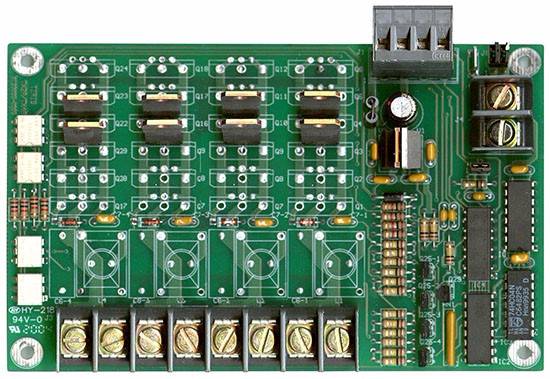
MUX Design by Oregon RFID™
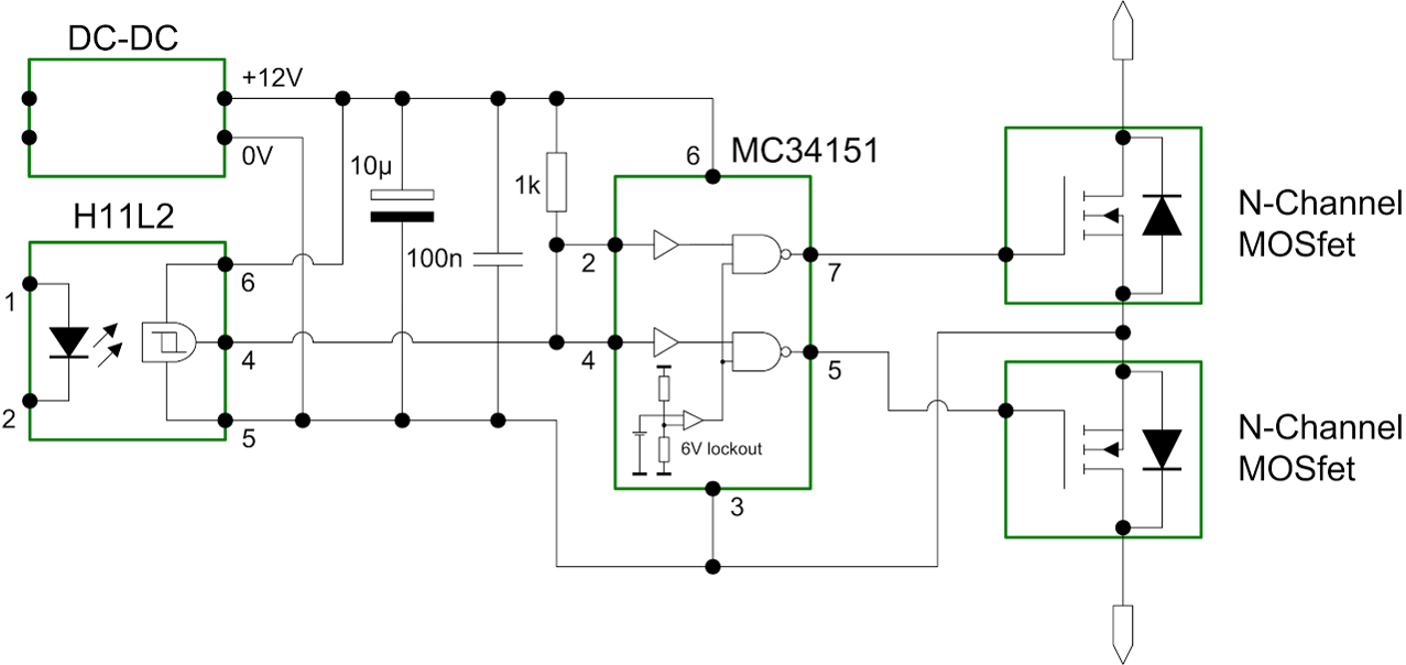
The multiplexer design used by Oregon RFID field units leaves much to be desired.
In order to gather all of the necessary data, at least two antennas will need to be deployed at each tracking site. Having multiple antennas allows the researcher to determine the direction of fish flowing in the river systems as well as provides redundancies. Because of this requirement, a multiplexer will exist in the final design to switch between multiple antennas. The current antenna switch by Texas Instruments is the RI-MOD-TX8A and has been successfully deployed. However, this switch has a high failure rate (>90% in well exposed sites) and reduces the read range of the antennas. Therefore, a new multiplexer design will need to be made in order to meet this requirement. This involves reverse engineering and characterizing the failure mode of the current design, and then using that information to design a new multiplexer.
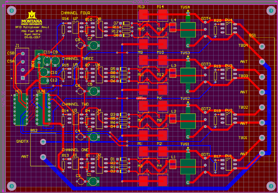
Proposed Multiplexer Design for Spring of 2017

A level-shifter was introduced after the CTL in order to step-up the CSA and CSB bit to 5V in order to meet the input voltage requirements of the CD74HC139 decoder. According to the multiplexer datasheet, the CSA and CSB bit have a range of 2.4V to 5V for what the CTL considers as high. Consequently, additional testing is required to see if the level shifter is actually necessary. For the time being, however, the datasheet conveys that it is necessary due to the large variance in output voltages.
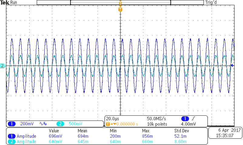
Multiplexer Update: Final Schematic and Switching event Waveform


In preliminary design testing, the power board and multiplexer were printed "barebone" and examined whether they achieved their expected design. Unfortunately, both the power board and multiplexer had precipitating issues that required only minor adjustments. For example, the power board was implemented with a voltage divider at the output of the 5V regulator. These were found to no longer be necessary since the specific chip purchased had this divider built into the chip. Once these were removed, the 5V regulator as well as the power board overall worked as anticipated. The cauer filter effectively removed any 134.2 kHz persisting at the input, the current sensor successfully reported an expected voltage to the ADC, and the 5V regulator and over-voltage protection circuit successfully power as well as isolated the Raspberry Pi. The multiplexer's inverter used to convert the decoder output from a low channel select to a high channel select originally didn't work. This was because the output of the inverter was configured as an open collector, which required a pull up resistor originally not included in the design. Once this was corrected, the multiplexer worked flawlessly.


