Power Board
The power board allocates power to the field unit’s Raspberry Pi, control module, and RFM unit. The board’s main responsibilities are to reject noise from the charge controller and suppress transient signals from either the input or the output. To ensure these obligations are realized, a third-order Cauer/Elliptic filter was selected for its cost-effectiveness, fast response time, and most importantly, its greater overall performance over its competition.
The Cauer Filter
 |
|
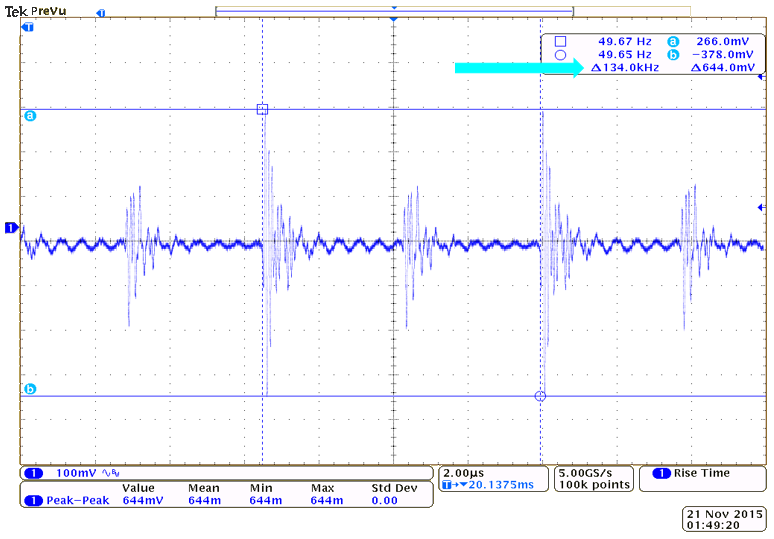
Unregulated Input Waveform for the RFM Transmitter |
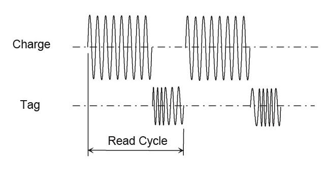
Half-Duplex (HDX) Protocol for Communicating with Fish PIT Transponders |
Considering that the transmitter operates at 134.2 kHz, it’s important that the noise from the charge controller is not carried through into the transmitter at this frequency. Hence, the Cauer notch filter will be employed in order to significantly attenuate noise at 134.2 kHz. Why a notch filter? Besides the dramatic transition attenuation slope, any other frequency other than 134.2 kHz is of no concern to us in this design. Additionally, by choosing sufficiently large capacitors, we will experiment with attempting to make the power board, and ultimately the input to the entire system, act as a constant voltage source. This will hopefully reduce the voltage sag whenever the transmitter switches on or off. The filter inductance will need to be chosen carefully as this is a high power system and any parasitic resistance inherent to the inductor coil will amplify the I2R loss at the just the input alone.
Voltage Regulator
The power board will have a linear voltage regulator to provide power to the Raspberry Pi data logger, which requires that the voltage be stepped down from 12 V to 5 V. Unfortunately, this configuration maximally has an efficiency of just 42%. This means that there’s nearly a 60% of input power wasted. This consequently generates heat within the regulator. As a result, alternative step down regulators are being considered. One such device is a switching regulator and can reach efficiencies of nearly 95%, but will introduce noise. With this in mind, however, the Raspberry Pi is durable enough to withstand whatever a buck converter may throw at it.
Proposed Power Board Schematic
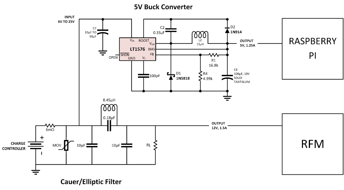
Proposed Power Board Circuit Schematic
Since the RFM unit is highly susceptible to noise, power conditioning plays a critical role in the functionality of the power board. This is primarily accomplished using a unique Cauer filter configuration designed to supply 12V at 1.5-1.6A to the RFM unit. This topology was chosen as per our adviser Andy Olson’s recommendation due to his experience with last year’s senior project group as well as from his own projects. Above the Cauer filter sits a 5V buck converter, which steps down 12V in order to sufficiently supply 12V at maximally 1.5A to the Raspberry Pi. The schematic shown was pulled from the datasheet for the LT1576 regulator.
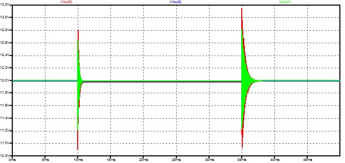
Transient Waveform for three Cauer Filters
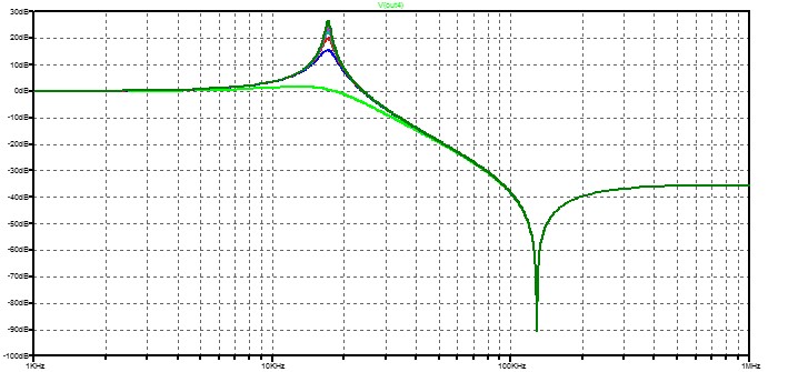
Frequency response of the top four Cauer Filters
Powerboard Update: 12 V and 5 V output waveforms
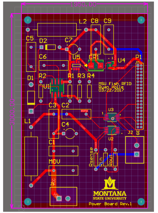
Final PCB Layout for Powerboard
In preliminary design testing, the power board and multiplexer were printed "barebone" and examined whether they achieved their expected design. Unfortunately, both the power board and multiplexer had precipitating issues that required only minor adjustments. For example, the power board was implemented with a voltage divider at the output of the 5V regulator. These were found to no longer be necessary since the specific chip purchased had this divider built into the chip. Once these were removed, the 5V regulator as well as the power board overall worked as anticipated. The cauer filter effectively removed any 134.2 kHz persisting at the input, the current sensor successfully reported an expected voltage to the ADC, and the 5V regulator and over-voltage protection circuit successfully power as well as isolated the Raspberry Pi. The multiplexer's inverter used to convert the decoder output from a low channel select to a high channel select originally didn't work. This was because the output of the inverter was configured as an open collector, which required a pull up resistor originally not included in the design. Once this was corrected, the multiplexer worked flawlessly.
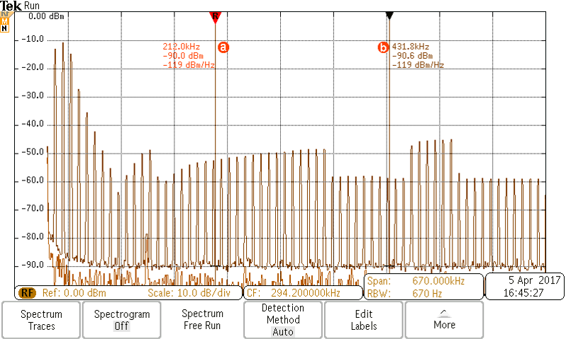
Frequency attenuation between 212 and 432 kHz.
At the 12 V output of the board, we see that we have a 30 dB attenuation at our desired frequencies.
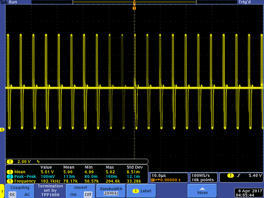
5V output waveform at Raspberry Pi GPIO pins
The 5 V output ports on the power board are shown to have met specifcations with up to .01 V difference of 5 V. This is critical for the proper functionality of the Raspberry Pi, the board requiring the 5 V. Without an accurate output, the board could be damaged as there will be minimal safeguards in place through powering the board with its own GPIO pinset, instead of using a micro-USB adapter like the previous group had done.
