Key Accomplishments
Microcontroller Research

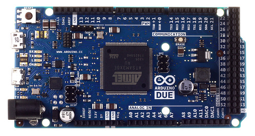
Overhead picture of the Arduino Due.
After looking at a variety of computer system solutions, we decided to choose the Arduino Due for our project. The Due has many features we need, which include an input supply voltage range of 7-15V, two digital to analog 12-bit converters, twelve analog to digital 12-bit converters, and a high clock speed of 84Mhz. Currently, simple tests are being done with the controller to figure out the time it takes to send a signal out the DAC and recieve it through the ADC. This test simulates a process of defoming the MEMS mirror and reading the light intensity through the photodiode.
Laser Diode and Photodiode

657 nm Laser Diode (taken from Thorlabs.com)
To start creating and experimenting with optical setups, a 658 nm laser was chosen along with a 3.6mm x 3.6mm photodiode. The 658 nm laser diode will allow us to see laser light for easier alignment of the MEMS mirror and lenses. Various mounts were also purchased to hold both of the diodes in place during testing.
Optical Setups

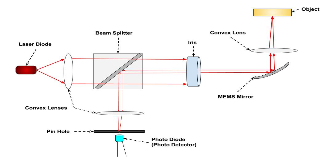
Diagram of a possible optical setup.
During our preliminary design review we presented three possible optical setup possibilities. One option was the setup shown to the right, which places the laser diode at a 90 degree angle to the MEMS mirror. The other setups include an in-line configuration, where the laser diode is directly in line with the MEMS mirror, for easy alignment. The last option is an in-line configuration that uses the laser diode as a photodiode. This setup proved to be too difficult and risky, so it was ruled out.
