Underwater Navigation
System
AUVSI Sub
Support Team
Chris
Scherr (EE)
Gavin
Lommatsch (EE)
Sam Hooson (EE)
Dr. Todd Kaiser (advisor)
Rigid Body Orientation
Visualization (1st Method: Euler
angles)
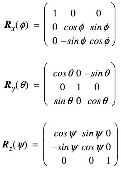
The team initially decided to use Euler angles to determine
the rigid body
orienation of the Sensortag, the main reason being the easy
conceptualization of Euler angles. The roll, pitch, and yaw
angles
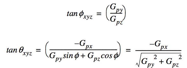
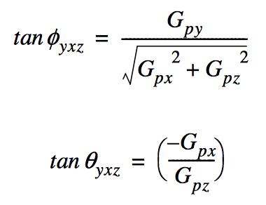
can be calculated from the static accelerometer and
magnetometer data. Roll and Pitch angles can be calculated from the
static accelerometer data alone. The equations for the roll and pitch
angles are shown below. Notice the difference between the same angles
in the equations. This is because the rotation sequence that is used is
crucial, and the sequence of rotations is not communitive.
A problem that can arise when using Euler angles and rotation
matrices to obtain orientation is Gimbal Lock. This phenomena is the
loss
of a degree of freedom, in which an axis of rotation locks with
another,
and cannot be calcualted once this occurs. Two graphical examples of
Gimbal lock are shown below. Since a main design goal was to create a
robust navigation system no matter the orientation of the IMU, the team
decided to look at other options for determining rigid body orientation.