
ECE Senior Design - Motorized Variable Attenuator (MVAT)
Abstract
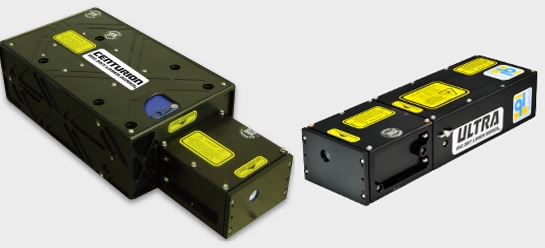
Quantel Pulsed Laser Solutions, a local company in Bozeman, is the leader in the rapidly advancing field of laser technology. Half of Quantels sales go to medical applications and the other half to industrial and scientific applications. Quantel Group is an international company with headquarters in France and subsidiaries in USA, Germany and in France. Quantel here in Bozeman, has had the idea for the past five to six years to take their current MVAT (Motorized Variable Attenuator) and redesign it to decrease not only the cost, but also the size of the unit.
An MVAT is an electromechanical assembly capable of adjusting laser emission energy from 100% to 0% of the laser's maximum output. Laser emission energy can be adjusted by changing the current supplied to the laser, but this also affects the beam quality. Using a MVAT, will keep the beam quality consistent while still allowing in adjusting the emission energy, which is very important for applications that need very precise lasers. Although Quantel has a current MVAT in production, they have many other projects to attend to causing the new MVAT design to lose priority. Therefore, Quantel has approached Dr. Maher with the idea to give Montana State University students the opportunity to develop a new design for the MVAT, which could potentially replace Quantel's existing MVAT.
Problem Statement
The goal of this project is to design and functionally demonstrate an improved MVAT assembly that reduces the size and cost of the existing Quantel MVAT.
The primary objectives are to reduce the material costs of an MVAT from $790 to approximately $500 and to reduce the MVAT overall size by 50%. The largest portion (30%) of the current materials production cost is attributed to the $240 motor within the assembly that rotates the waveplate. Emphasis will be placed on reducing the MVAT cost by using a different motor. MVAT assembly size reduction can also be realized by choosing a smaller motor since the current motor makes up most of the MVAT�s current length.
The secondary requirements of the new MVAT design are to maintain or improve the current waveplate rotation capabilities, position sensing abilities, and enclosure design. The MVAT provides approximately 1,040 incremental steps of the rotating waveplate from 0 to 45 degrees. The rotation of the waveplate from 0 to 45 degrees will yield, respectively, 100% transmission to 0% transmission of the laser energy. Accurate position sensing of the waveplate is required to determine the angle and the corresponding percent transmission of the laser. The motor will ideally be able to perform the full sweep from 0% transmission to 100% transmission in less than 5 seconds. Finally, in order to protect the optics in the system from any particle generation and outgassing components, the design must eliminate these as risk factors or implement controls or isolation techniques to prevent them from interfering with laser optics.
Goals & Constraints
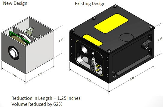
The two primary goals of this project are to reduce the size and cost of the existing MVAT assembly, while maintaining the tough, rugged, reliable and marketable characteristics that are known of Quantel products. The current MVAT costs approximately $790 in materials to produce. To be economically viable, the production cost of the new MVAT assembly will have to be reduced to around $500. The size of the assembly will also have to be reduced by 50% from the current dimensions of L2.7'' x W1.9'' x H2.2'', with the length being the primary reduction factor.
- Reduce materials costs from $790 to $500 and labor costs from $54 to $25 per MVAT assembly
- Reduce size of MVAT by 50% of current size, with shortened length being the primary reduction factor
- Provide at least 1040 incremental steps from 0% to 100% transmission
- Operate on 24VDC with a max 7W power consumption
- Have a 5 second or less response time from 0% to 100% transmission
Identified constraints are:
- Fit in the existing MVAT housing of L2.7"xW1.9"xH2.2"
- Isolate outgassing components, and protect laser beam from dust and other particles created by motor
- Capable of determining the percent transmission of the laser at any time through position sensing of the waveplate
- Cost less than the existing MVAT of $790 for materials plus $54 for labor
- Interface with the existing software used to drive Quantel lasers
Current Design
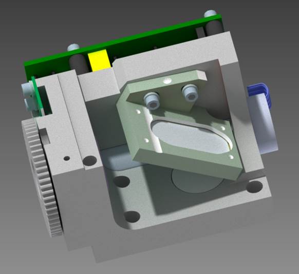
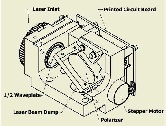
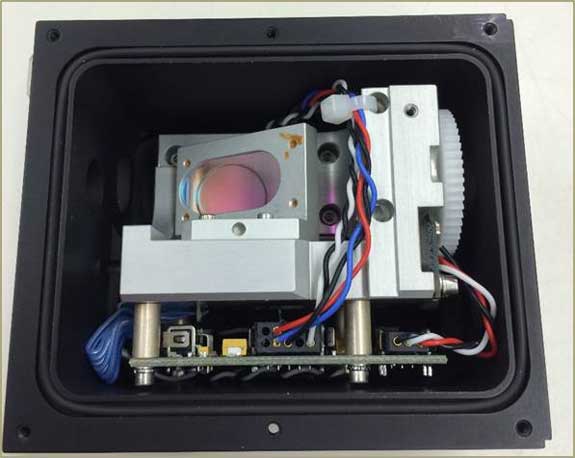
The MVAT electronics controlling the half waveplate consist of a motor to physically rotate the waveplate, an encoder to determine motor positioning, and a sensor to provide position feedback. The optical components include a rotatable half waveplate, an angled polarizer, and a beam dump. These devices all work together in a sealed environment provided by the MVAT housing; a modular case that allows for bolt-on addition to many of Quantel�s industrial lasers. This housing does have a removable lid for device repair, demonstration, and modification.
The interface for controlling the device is external, as is controller software. This software is provided with the completed device and must be shown to consistently provide desired control and resolution. Typical industrial-level electromagnetic interference and other electrical noise must not interfere with device operation. A linearization must be performed in order to match the power output to a given user input, because intensity of the transmitted light is not intrinsically related to the angle of the waveplate as a linear function.
The motor has access to a 24 Volt DC rail, with a maximum power consumption of less than 7 Watts. Any device that transforms the current-voltage characteristics of the device is to be mounted internally. The device must not create any particulates that could interfere with optical performance. Therefore, any apparatus that is known to outgas must be sealed from the optics in order to maintain desired operation and device life. The motor and associated controller must produce highly reliable and repeatable results.

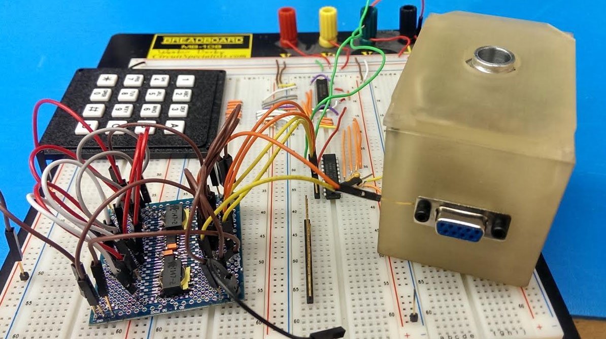
Intermediate Prototypes
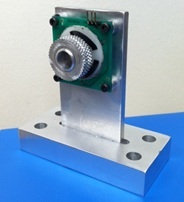
Prototype 1Created: November 2013
|
|
-
Issues
- Shaft would not rotate when horizontal. Weak rotation was achieved when shaft was positioned vertically.
- Steel pins were brittle and broke easily in assembly, resulting in a need to re-drill pinholes in the aluminum shaft.
- Achieving optimal force from the Bellevue spring was difficult.
-
Solutions
- Alignment: The shaft would rotate better when aligned with the stator. Any axial offset drastically decreased performance.
- Pin material: Nylon pins were ordered to replace the brittle steel pins. These nylon pins were much more effective, and were used for the remainder of the project.
- Adjustability: A greater ability to adjust spring force would make optimization much easier in later models.
Note: Photo used above is actually of the second prototype with the threaded shaft. However, the test stand used is the same, and the design was similar. The photo is used to give an idea of what the original prototype looked like before it was replaced by the second prototype.
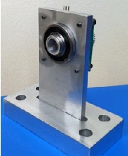
Prototype 2Created: November 2013
|
|
-
Issues
- Shaft would not rotate due to friction of alignment pins on rotor
- The wear pattern was uneven on the rotors.
- A high-pitched noise emanated from the rotors.
-
Solutions
- Alignment: The shaft would rotate better when aligned with the stator. Any axial offset drastically decreased performance.
- Pin material: Nylon pins were ordered to replace the brittle steel pins. These nylon pins were much more effective, and were used for the remainder of the project.
- Adjustability: A greater ability to adjust spring force would make optimization much easier in later models.
Tape: The old friction tape from the original PCB motor assembly given to us by Quantel was applied, and the noise was eliminated and motor operation became much smoother. Other friction tapes were ordered and tested, but the original PCB tape seemed to work the best.
Note: Photo used above is actually of the second prototype with the threaded shaft. However, the test stand used is the same, and the design was similar. The photo is used to give an idea of what the original prototype looked like before it was replaced by the second prototype.
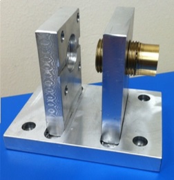
Prototype 3Created: January 2014
|
|
-
Issues
PCB motor did not have torque to turn against the O-ring seal inside the threaded brass insert with slight compression. The brass insert was reamed out until the shaft would turn, but at that point there was a visible gap between part of the O-ring and the brass piece. Alignment was partially at fault. With the brass piece held just right by hand, the shaft would turn.
-
Solutions
Alignment: For the next prototype we assembled the test stand and drilled the entire stand as one bolted assembly in order to ensure concentricity of the holes.
Delrin Inserts: Because the coefficient of friction of an O-ring on an aluminum surface is much higher than an O-ring on a greased delrin surface, the next prototype incorporated delrin inserts with the O-rings tightly placed on the shaft.
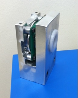
Created: February 2014
|
|
-
Issues
Even with the O-rings turning against a greased delrin surface, the shaft would not turn if ANY compression was placed on the O-rings. The shaft was tested with a slight compression on one O-ring, and would not turn. The delrin insert was then reamed out to a larger diameter, then tested, then the process was repeated until the shaft would turn. With one seal and a barely contacting O-ring the shaft would turn slightly. With two seals the shaft would not turn until the inserts were reamed out to the point that that there was a visible gap between the O-rings and the delrin inserts. This proved almost conclusively that the PCB motor does not have the torque to turn against any kind of O-ring seal.*
-
Solutions
Prove that the stator does not generate significant particulate matter. If it does generate particulate matter, some form of brush seal, or potentially a dual-stator design may be adequate.
* There is a small possibility that if all other variables are perfectly optimized, and 5 Volt electrical components are used instead of the 2.5 Volt components used in our circuit, slightly more torque could be generated by the PCB stator. However, the performance with rubber O-ring seals is unreliable at best, and is not recommended.
Created: February 2014
-
Alignment:
Performance is greatly increased if the rotors and shaft are concentric with the PCB stator. Our recommended solution
to align the shaft and rotors is by use of a single Bearing mounted on one side of the shaft.
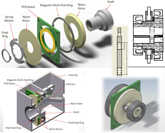
Rotor Connection: There are multiple options for attaching a rotor to the shaft. What we found to work best is machining one rotor directly into the shaft (by machining the entire shaft our of 2� diameter aluminum). The second rotor is mounted on the opposite side of the PCB stator and aligned with three nylon pins. The rotor should be free to slide axially on these pins, but any angular rotation should be restricted. The nylon makes assembly easier than brittle steel pins. Another possible option, if sealing is not an issue, would be a key-and-groove connection.
Spring Force: Spring force is an issue, and adjustability is critical for prototype development. However, for bulk manufacturing the recommended solution is to use a retaining ring and groove at a fixed optimal distance. According to one PCB test graph, the spring force PCB recommends is 4 Newtons. However, it is recommended to optimize the spring force specifically for the final design.
Rotor: Flatness seemed to be the biggest issue in rotor performance. We found that the best rotor was a machined steel washer purchased at Ace Hardware. However, PCB motors generally uses a plastic rotor, but it was difficult for us to achieve a flat surface after any work was done on a plastic rotor.
Tape: PCB motors uses a fiberglass tape with a silicone adhesive, .12 mm backing thickness, and .165 mm total thickness. The cost from PCB motors is $108 for a 50 mm x 50 m roll, which amounts to roughly 20 cents per MVAT assembly. The tape that PCB uses is H-old GL.96 glass fiber enforced adhesive tape with an alu layer.
Torque/Sealing: The PCB stator provides very little torque, so it is recommended to keep torque requirements at an absolute minimum. Seals, mechanical position sensors, or any other torque-using attachment should be avoided if possible.
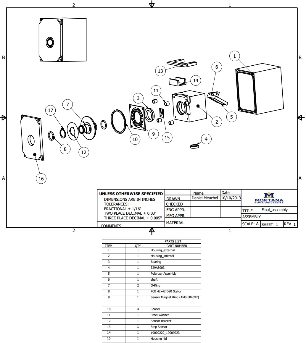
New Design
The primary requirements are to reduce the material costs of an MVAT from $790 to approximately $500 and to reduce the MVAT overall size by 50%. The largest portion (30%) of the current materials production cost is attributed to the $240 cost of the motor within the assembly that rotates the waveplate. Emphasis will be placed on reducing the MVAT cost by using a different motor. MVAT assembly size reduction can also be realized by choosing a smaller motor since the current motor makes up most of the length of the MVAT.
The secondary requirements of the new MVAT design are to maintain or improve the current waveplate rotation capabilities, position sensing abilities, and enclosure design. The MVAT provides approximately 1,040 incremental steps of the rotating waveplate from 0 degrees to 45 degrees. The rotation of the waveplate by 45 degrees will produce 0% transmission to 100% transmission of the laser energy.
Testing
-
Calibration: Graph power output � vs. � number of steps. Collect approximately 100 data points showing the entire range of motion from 0-100% transmission.
- Fit a curve to the graph, and (potentially) program the function into the control board to compensate for nonlinearity.
- Potentially may need to devise some sort of safety shut-off so that the motor doesn�t run continuously for more than 20 seconds if the shaft should stall for any reason while running.
Consistency: Measure power output at 90% transmission, 50% transmission, 10% transmission. Repeat 20 times and calculate error.
Additional position sensors can be implemented to further distinguish between laser output discrepancies and positioning error.
Reliability: Program motor to cycle from 0-100% transmission with 2 second pause between cycles. Run for 24-48 hours.
Precision: Depending on the precision of the measuring equipment, show that power output can be controlled to within 0.1% (1000 steps).
Team
Team members:
- Samuel Thompson (ME)
- Michael Raveling (ME)
- Daniel Meuchel (MET)
- Weston Derby (EE/CpE)
- Seth Smith (EE)
This project is sponsored by Quantel inc. and Montana State University College of Engineering, Electrical and Computer Engineering Department